The Badge

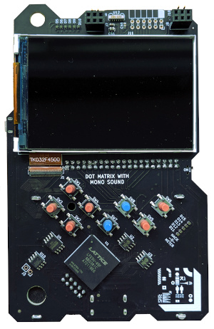
This year’s Superconference has the badge - Large FPGA-based delight. Here’s the hackaday announcement.
Features
- ECP5 LFE5U-45F-8BG381C
- 45k LUTS
- Embedded RAM 108 x 18kb 1.9Mb
- Distributed RAM 351kb
- 18 x 18 multipliers - 72
- 480x320 screen MIPI Type B
- 8 buttons - that can be used as D-pad and a/b/select/start
- 32MBit Flash W25Q128JVSIQ
- 2 x 64Mb (8M x 8) RAM LY68L6400SLIT (16MB)
- Audio Amp - NS8002
- IRDA RPM973-h11
- LEDs
- Pmod 12 pin port
Badge SoC
@sprite_tm has built an entire SoC on the badge, with a twin core RiscV processor, a fancy GPU, lots of memory and, amazingly, capable of running regular GCC compiled C-code!
The Repo for all this is - https://github.com/Spritetm/hadbadge2019_fpgasoc
Most Supercon party-goers will want to work at this level with these amazing tools.
Badge FPGA

For those interested in stretching their Verilog FPGA skills there is the FPGA itself. Be warned, however, Verilog is hard. It’s not like just picking up a new programming language. Your brain needs to be rewired. If you haven’t yet undergone that procedure, take it slow and aim appropriately.
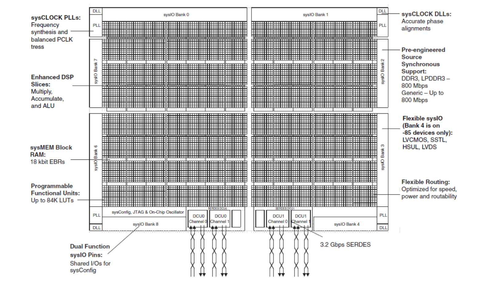
Warnings aside, the FPGA itself is an FPGA coder’s delight. Even if the above is the least sexy way to depict it. The ECP5 is a large device (high LUT count) for it’s power and price. All development can be done using open source tools.
Read the general documentation about the code to get an idea of how the source code is organized.
There are several projects specifically ready to load into hardware. Prototype V2 Hardware Only, presently
led_blink- the security blanket of projects. Use this to make sure everything is set up. It’s small, builds and downloads quickly and most importantly unlocks the “Hack O Meter” achievement by blinking one of the front LEDs. Uses 0% of the LUT supply (25/21924 slices).usb_loopback- adds a USB port to the FPGA at runtime. Uses 3% of FPGA LUT supply.lcd_pattern- puts a few patterns on the LCD screen. Up button configures the LCD, Bottom button clears it, Left adds a grid pattern and Right adds a color block. 3% FPGA LUT usage.camera_2_lcd- connects an MT9V022 or MT9V034 camera to the LCD. Up button to start the LCD. Left button to connect camera stream to LCD. 7% FPGA LUT usage
All these projects reassuringly blink a front LED, they also use SW6 to trigger a configuration process.
The make files have make flash to invoke tinyprog to do a download. They also have make boot which invokes tinyprog -b to restart a board in configure mode.
Supporting these projects, the core source code currently available is as follows:
- LCD Driver Documentation
- I2C Master & Slave Documentation
- Camera Driver Documentation
- USB CDC (originally from Luke Valenty) Documentation
- UART (originally from Open Cores)
Documentation is currently a little sparse.
There are some projects in the respective directories to test the above in simulators. These tests are very exhaustive, but there may well still be bugs. These are fiddly bits of code (especially the USB and I2C). The UART and USB codebases have been tested in ECP5, iCE40, and Xilinx hardware, and so should be considered fairly robust. The I2C Slave has not been tested in hardware at all since it mostly exists to test the I2C Master in simulation. Both the LCD and Camera have proxies (code that connects to the driver and represents the actual hardware) for testing. These can be very handy for testing new functionality and to ensure things haven’t broken when you modify it.
Additional Code to be released shortly
- SPI Master and Slave
- Pipe library for manipulating pipelines of data
- Image handling functions to pipe / modify / combine video
- Fast Comms code for 100Mb/s reliable communication board to board
All new code is released under Apache 2.0
Tools
There are many tools required for this project.
Normally for an ECP5 device you would have the choice of working with Lattice’s Diamond tools, but unfortunately the badge has a tiny bug that prevents this from working. Even more sadly, the most natural workaround is prevented from functioning by a bug in Diamond. Argh! This is not really a big deal since the Open Source tools are excellent. These instructions will therefore focus on the OSS tools for now.
All the code in this repo has been developed in Visual Studio Code with extensions to assist with Verilog editing. However, any editor will do.
All code has been built in a command window separate from the editor.
To build an image for the FPGA at a high level you need the following:
- something to parse all your Verilog files and to translate the code into actual hardware functionality. This tool is yosys
- something to take all the hardware functionality and map it onto the resources of the ECP5. We’ll be using nextpnr with project trellis (which adapts nextpnr to the ECP5)
- something to download code to the board. tinyprog
Additional tools needed for serious coding
- Verilator - fast Verilog simulator with connection to C/C++. Ideal for simulating large complex systems (Like the Badge SoC). Also very good for checking code (
--lint-only) - Icarus - less fast, cycle accurate simulator perfect for unit tests.
- GTKWave - tool for viewing a complete map of all activity of a program on a timeline.
See the FPGA Tools section for more details